15 loop diagram questions Control loop valve flow typical works Control pressure level loop loops steam problem instrumentationtools setpoint pic begins psi measured rise value above should if
P&ID Process Diagram, Piping, Symbol, Abbreviation, Equipment, Pump
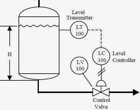
P&id process diagram, piping, symbol, abbreviation, equipment, pump What are control valves? How a typical control valve loop works ~ learning instrumentation and
Loop control symbol process example diagram valve simple pump piping understanding standard equipment line
Valves transmitterP&id process diagram, piping, symbol, abbreviation, equipment, pump How a typical control valve loop works ~ learning instrumentation andBasics of a control loop.
Schematic diagram of a control valvePressure control loop wiring connections Flow valve direction control gas valves oil close open engineering fto actuator failInstrumentation typical.
Loops schematic output diagram input speedometer
7.3 loop diagrams-instrumentation documentsWhat is a control valve and how does it effect my control loop Questions instrumentation instrumentationtoolsDiagnosing and solving control problems.
Instrumentation loop diagramsLoop control valve diagram block instrumentation typical engineering learning Level controller tuningLoop instrumentation diagrams instrumentationtools.

Oil and gas engineering: flow direction of control valves
Loop control symbol process example diagram valve simple pump piping understanding standard line equipmentControl loop valve does effect affect Practical process control system questions & answersHow a process control loop works in automatic control systems.
Control process system flow loop liquid instrumentation signal valve controller pressure transmitter rate instrument pipe air practical answers questions outputControl valve loops – instrumentation and control engineering Valves loopPool valve spa valves way ball system diverter port set pools spas repair suction diagram plumbing water basic manual actuated.

Wiring instrumentation
Control loops coupled dynamicallyProblem on pressure and level control loops Loop instrumentation diagrams compressor surgeExamples of control loops (a) schematic of a simple control loop. the.
Control valve loopsInstrumentation loop diagrams Loop control valve pressure typicalInstrumentation dcs instrument control instrumentationtools.

How a typical control valve loop works ~ learning instrumentation and
.
.


Pool-n-Spa-valves - Assured Automation

Oil and Gas Engineering: Flow Direction of Control Valves

Instrumentation Loop Diagrams - InstrumentationTools

Schematic diagram of a control valve | Download Scientific Diagram

What are Control Valves? | Selection and Types of Control Valves – What

What is a Control Valve and How Does It Effect My Control Loop

Basics of a Control Loop | Control engineering, Process control, Control